

Introduction
Longevity of aboveground storage tank service life is dependent on quality control of its initial construction as well as timeliness and effectiveness of periodic internal and external inspections. API Standard 653 Tank Inspection, Repair, Alteration, and Reconstruction describes in detail the minimum requirements for upkeep and maintenance of an AST. Tank evaluations include items such as tank bottom thickness, minimum remaining plate thickness, nozzle assessments, shell out-of-plane settlement, edge, and bottom settlement.
Traditional inspection methodologies and techniques require tanks to be taken out of service for preparation and inspection at a specified time period. Unfortunately, traditional time based out of service tank inspection methods disrupt commercial operations and are reactive, expensive, and carry inherent health, safety, and environmental risk in order to perform.
On-stream robotic tank inspections offer a much more proactive approach to tank quality and risk management programs with improved commercial economics that should be built into tank owner/operators quality program and AST inspections. Robotic inspections, when applied properly, better align with corporate economic and ESG goals by removing personnel from unnecessary and unsafe work in confined spaces, reducing or eliminating air and product emissions from tanks, improving tank utilization and uptime, safely extending out of service dates and tank life, and reducing overall inspection and repair cost.
Evolution in tank integrity practices
The history of tank design and maintenance practices evolution has more than 150 years. During those years a sequence of events based on incidents and subsequent industry committees responses has shaped what we have today in terms of best practices and standards for tank design, integrity management and maintenance.
Figure 1. Tanks in History – A Journey of Events and Actions.
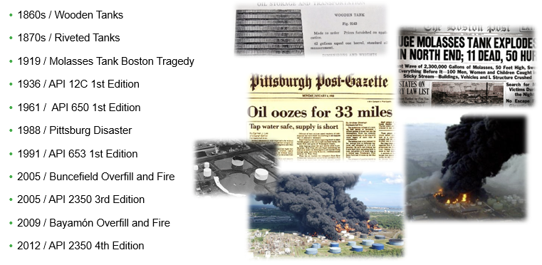
The API Standard 653 Tank Inspection, Repair, Alteration, and Reconstruction 1991 First Edition, document that describes in detail the minimum requirements to manage the integrity of ASTs has only 31 years of evolution and started as the response of the US congress to the severe environmental impact generated for the shell collapse of a reconstructed tank that released 92 million barrels of diesel fuel to the Monongahela River in Pennsylvania, USA in 1988.
The above-mentioned incident known as the “Pittsburg Disaster” set the stage for the intent, scope and focus of the API 653. The intent was, and continues to be, to provide guidance establishing the minimum requirements for the integrity management of an AST. The scope obviously and like other API equipment integrity management documents had elements of metal loss monitoring and remaining life considerations, but in addition to that included considerations for repairs and reconstruction. And the focus was and continues to be on avoidance of environmental consequences caused by the release of the tank content.
The environmental consequences focus makes the floor of the AST a critical component as leaks cannot be detected by external inspection, and then the access to the AST floor for inspection and eventual repairs drives the internal inspection intervals, which has been one of the areas where more changes had occurred in the API-653 over the last 3 decades.
Brief history of API 653 Internal Inspection Intervals criteria:
- Originally API 653 called for a maximum of 20 years between internal inspections and 10 years if corrosion rates were not known.
- Started as Section 4.4.2 Inspection Intervals in original 1991 1st Edition document
- Was still in Section 4.4.2 in 2nd Edition originally published in 1995:
- “4.4.2.2 When corrosion rates are not known and similar service experience is not available to determine the bottom plate minimum thickness at the next inspection, the actual bottom thickness shall be determined by inspection(s) within the next 10 years of tank operation to establish corrosion rates.”
- The 2nd Edition addendums also introduced the concept of Risk Based Inspection (RBI) as an alternative to time-based criteria.
- The 3rd Edition of API 653 was published in December 2001; major renumbering and reorganization was done.
- This is when Section 6.4.2.1 was created, and Table 4.1 renamed Table 6.1; Section 4.4.2.2 was renumbered as 6.4.2.2
- In 6.4.1.2 a prevision for in-service inspections was added as: “If the internal inspection is required solely for the purpose of determining the condition and integrity of the tank bottom, the internal inspection may be accomplished with the tank in-service utilizing various ultrasonic robotic thickness measurement and other onstream inspection methods capable of assessing the thickness of the tank bottom, in combination with methods capable of assessing tank bottom integrity as described in 4.4.1.”
- The language of Section 6.4.2.2 changed in 2003:
- 6.4.2.2 When corrosion rates are not known and similar service experience is not available to estimate the bottom plate minimum thickness at the next inspection, the internal inspection interval shall not exceed 10 years.
- The 4th Edition of API 653 was published in April 2009.
- This is when Section 6.4.2.1 was first published in its current form. Up to this point API-653 was running in parallel with other API inspection codes (510 and 570) on inspection intervals based on corrosion rates, similar service, and RBI. The safeguards in API 653 addressed the opportunity to enhance the bottom design of an AST for new fabrication and even more relevant for “retrofits” during tank turnarounds. A big part of the differentiation of API 653 from the other inspection codes and in fact the biggest credit to extend internal inspection intervals was the opportunity to reduce consequences with release prevention barriers installed in components with no access while in service.
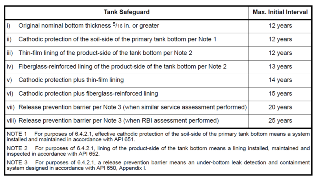
- 6.4.2.1 The interval from initial service until the initial internal inspection shall not exceed 10 years. Alternatively, when either a risk-based inspection (RBI) assessment per 6.4.2.4, or a similar service assessment per Annex H is performed, and the tank has one of the following leak prevention, detection, or containment safeguards, the initial internal inspection interval shall not exceed the applicable maximum interval as shown below.
- The Table below was first published
Table 1 – API 653 4th Edition – Tank Safeguards
- API 653 4th Edition, Addendum 2 was published in January 2012
- This is when the current language was first introduced
- This is also the first time the Table was named 6.1 – Tank Safeguard
- 6.4.2.1 Initial Internal Inspection Interval
- The initial internal inspection intervals for newly constructed tanks and/or refurbished tanks shall be established either per 6.4.2.1.1 or 6.4.2.1.2
- From January 2012:
- Owner/Operators must be in compliance with these new requirements by January 2017
- 6.4.2.1.1 The interval from initial service date until the first internal inspection shall not exceed 10 years unless a tank has one or more of the leak prevention, detection, corrosion mitigation or containment safeguards listed in Table 6.1. The initial internal inspection date shall be based on incremental credits for the additional safeguards in Table 6.1 which are cumulative.
Table 2 – API 653 4th Edition, Addendum 2 – Table 6.1 Tank Safeguards
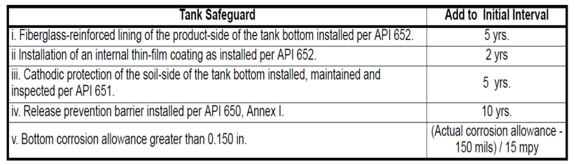
- For example, the maximum interval for a 1/4 in. bottom that has a release prevention barrier, and a fiberglass lining would be determined as follows:
- 10 years (initial) + 5 years (fiberglass lining) + 10 years (release prevention barrier) = 25 years.
- The initial inspection interval shall not exceed 20 years for tanks without a Release Prevention Barrier, or 30 years for tanks with a Release Prevention Barrier.
- API 653 5th Edition was published November 2014
- Added stainless steel bottoms to Table 6.1
- In 2019 added allowance for Initial bottoms > 0.25 in
Important Milestones in the API 653 Internal Inspection Intervals criteria:
- Going back to the original 1991 document, credit was given for Fiber Reinforced Plastic (FRP) and it is still there.
- In 2009, credit was given for Release Prevention Barrier (RPB), Cathodic Protection (CP) and thin film, the same as today.
- Credit for bottoms thicker than 0.250” given in 2019.
The API 653 environmental focus and the consequent emphasis in the reduction of the risk to develop an “un-contained” leak from the floor as a component with limited access for inspection, monitoring and leak detection led into the development of engineering controls and mitigations for both likelihood and the consequence of the floor failure.
On the likelihood of failure mitigations, the corrosion control measures for both product side and under side were included as coatings for the product side and CP for the underside. On the consequences of failure mitigations, the RPB was included as a way to contain the leak avoiding contact with the soil and potential migration to waterways or aquifers.
From the reliability perspective the extended initial internal inspection interval considers the safeguards and design enhancements that are in place to protect the tank and limit the potential for loss of containment. Linings and coatings provide a barrier from the product interacting with the tank bottom, reducing corrosion rates and lowering the potential for product release. The tank bottom itself can be constructed using corrosion-resistant materials or larger plate thicknesses, which can greatly improve the tank’s longevity, especially when combined with cathodic protection systems to reduce the corrosion growth rate within the tank. Release prevention barriers are installed underneath the tank to contain any product that may be released from a failed tank bottom, limiting the environmental impact should a tank bottom fail. Thus, those tanks with three layers of protection (internal lining, tank bottom with cathodic protection, and release prevention barrier) present a much lower risk to the environment than the single barrier (tank bottom with cathodic protection)
The above-mentioned mitigations meet the intent of risk reduction, creating the opportunity to manage tank integrity based on risk with the extension of initial internal inspection intervals and the subsequent inspection intervals by using the RBI methodology and Similar Service Assessments reducing the total number of internal tank inspections to be performed. Each internal inspection requires the tank to be shut down, drained, put through an extensive cleaning program, inspected, repaired (if required) and then placed back into service. These steps all fall outside of regular daily operations and have the potential for damaging the tank, its ancillary equipment, or causing environmental exposure and/or small releases of product. These operations also subject personnel to health and safety risks, as entering the tanks (i.e., confined spaces) for cleaning and inspections includes some inherent risk. Minimizing these operations through only inspecting the highest-risk tanks will help to decrease risk to both the equipment and inspection personnel. Reducing the overall number of tank inspections will also help to limit the environmental impact of the inspections, which may affect the environment through impacting factors such as air quality, greenhouse gas emissions, and noise.
From a cost perspective, it is anticipated that the average initial internal inspection interval for newly constructed tanks, existing tanks with a newly installed bottom and the subsequent internal inspection intervals for “good actor tanks” will increase. Performing fewer inspections on an annualized basis will help to reduce inspection costs for those tanks with sufficient safeguards in place or for those with historical data that supports low likelihood of failure to warrant extended internal inspection intervals. In addition to the direct costs associated with tank inspection, fewer tank outages will help to maintain steady product delivery through limiting tank outages and downtime. The cost benefit will also encourage tank owner / users to incorporate additional safeguards into the design of new tanks to be constructed in the future and develop / implement tank integrity program based on risk. Thus, implementation of risk-based approach will limit the overall inspection cost for the owner / user tank fleet while minimizing potential service interruptions and more importantly reducing the exposure to safety incidents, the generation of hazardous materials waste and emissions to the atmosphere.
A tank integrity program based on risk includes elements of assessment methodologies and technology to gather and process representative data in a non-invasive and non-disrupting way to the tank operations. API 653 provides references for RBI assessment methodologies and the tank owner / users can select, develop, and implement the risk-based approach that better fits their case. On the technology to support effective and efficient data gathering, non-intrusive inspection and nondestructive examinations (NDE) are being developed to get information of the floor and the internal surface of the shell. Also, robotic inspections have been developed to assist in the data gathering by introducing un-manned robots inside the tank in many cases allowing the tank to continue in-service. At this point owner / users have several tools available in the toolbox to continue optimizing their tank integrity management programs.
Industry trends in tank integrity and reliability metrics
The tank integrity trend is going from condition based to risk based. Where condition-based approaches are not considering differences in consequence of a failure for different tanks; and the inspection event intervals are based on time arbitrarily set per regulations, codes, standards, or company policies. Also condition based approaches rely on trending degradation mechanisms that cannot always be effectively modeled to produce representative rates of degradation. The risk-based condition approaches include analysis of consequences beyond the loss of containment event, and analysis of likelihood based on probability.
The risk-based approach is allowing tank owner / users to identify and differentiate from good actor and bad actor tanks. The optimization of integrity programs for good actor tanks is now occurring showing interesting and promising trends on extension of internal inspection intervals.
Table 3 – Internal Inspection Intervals Trends
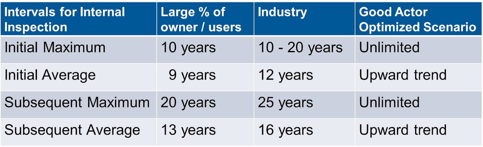
The “Unlimited” maximum internal inspection interval for good actors is achievable based on a well developed and implemented tank integrity program with clearly defined actions for different stages and stakeholders. Starting with the design and construction of new tanks with safeguards, executing the retrofit of existing tanks to incorporate mitigations; and implementing risk assessments supported with data gathered from non-intrusive / in-service inspections. Table 4 below shows a summary of actions toward the optimization of the tank integrity program.
Table 4 – Good Actor Tanks – 3 Actions toward optimization
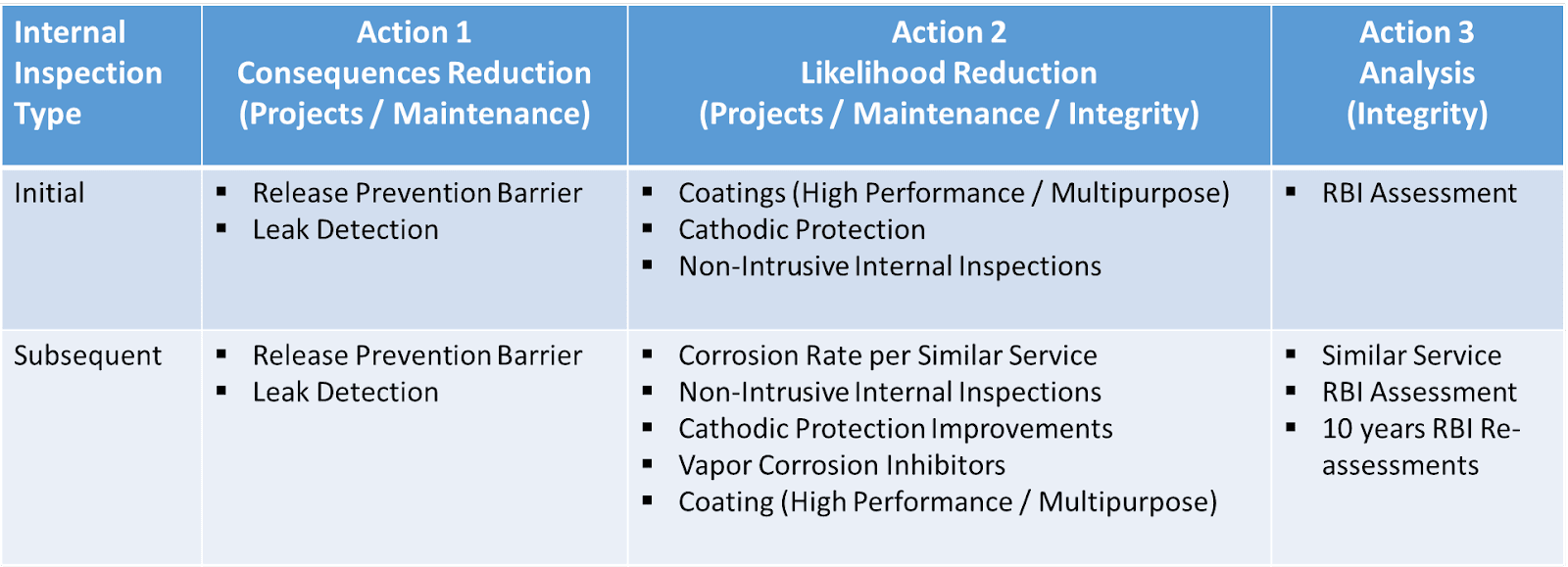
These actions toward optimization require investment in assessments to identify the good actor tanks, but then the savings from the internal inspection intervals freed up resources for investments to design and construct new tanks with safeguards and even more impactful convert bad actors to good actors by retrofitting them with mitigations. The non-intrusive / in-service inspections based on externally applied NDE, or robotic inspections provides the opportunity to have data points on good actors to support continuity in-service and have data on bad actors to develop optimized scope of work of repairs before taking them out of service.
Many tank owner / users are reporting short term savings in the first 5 years of the implementation of tank integrity risk-based programs by identification of good actor tanks with internal inspection intervals extended for at least 5% of the tanks that were planned to be taken out of service. Average saving per deferred tank has been identified as $400K, while the tank RBI assessment investment per deferred tank has been identified around 1% of the out of service maintenance and inspection costs. The cost of non-intrusive / in-service inspections based on externally applied NDE, and robotic inspections has been identified around 10% of the out of service maintenance and inspection costs.
Other side benefits that tank owner / users are experiencing by implementing tank integrity risk-based programs is a better understanding of the risk profile across their tank fleets with definition of relative risk rank for all tanks, which is helping them to level load annual tank maintenance, while providing more operational and commercial flexibility.
Other intangible benefits are around lead industry optimization initiatives influencing industry organizations and regulators by building risk management case studies incorporating new technology options.
The latest in robotic technology for tanks and challenges for implementation
Robotic Inspection Value Drivers and Use Cases
Robotic in-service inspections can supplement, complement and may ultimately be capable of replacing traditional out-of-service tank inspections. The use cases and value drivers for a robotic in-service inspection are numerous, as summarized below:
- Improved Health, Safety and Environmental Performance
Typical out-of-service inspections on aboveground storage tanks require that the tank be vented, emptied, cleaned, and waste remediated. These actions create potential for leaks and spills and require many dangerous labor hours of work in confined space even before inspections commence. In many cases, robotic in-service tank inspections can be performed without the need to empty or clean the tank and eliminates the need for confined space entries. Emissions are negligible as the robot is launched and recovered through a 24” manway on top of the tank which is again covered by a temporary manway plate during inspection.
- Proactive vs Time Based Information and Decision Making
Conducting robotic tank inspections proactively ahead of planned out of service compliance dates regulated by governmental bodies provides owner operators several significant advantages. Very valuable quantitative and qualitative data of the tank is acquired using a variety of robotic payload sensors including phased array ultrasonic, pressure and temperature sensors, echo-sounders, and high-resolution video cameras. This sensor data supports evaluation of tank bottom thickness, tank bottom settlement, shell wall and internal appurtenances, product quality, sediment and sludge levels, coatings, and cathodic protection system effectiveness.
Robotic inspections planned ahead of out of service compliance dates provide valuable data that support decisions that improve or validate preventative maintenance programs such as coatings and cathodic protection systems, extend tank out of service repair dates to future years, or even extend planned tank life expectations.
Inspection data acquired ahead of planned out of service dates by robotics may also support a decision to take a tank out of service for required maintenance and repairs. Fortunately, this information may prevent an unforeseen tank failure that gains scrutiny from internal and external stakeholders and damages reputation. Data provided well ahead of out of service repairs can ultimately level load inspection and repair budgets, improve tank utilization and downtime, level load tank downtime and economics, support proactive vs reactive supply chain and materials management for repairs.
- API 653, EEMUA 159, and Risk Based Inspection Reports
Robotic inspections provide critical data to support API 653, EEMUA 159, or RBI reports as part of an operator’s quality program and regulatory compliance requirements. The primary objective is to ensure the integrity of the tank during its future operating state through a thorough external and internal inspection. External inspections should include a visual inspection, an analysis of shell thickness employing ultrasonic tests as well as an inspection of the cathodic protection. In addition to external inspection, an internal inspection of the tank should be carried out, mainly to assess the integrity of the tank bottom. The frequency of inspections will be based on the history of the tank in service, its corrosion rates, and the type of inspection considered.
d. Tank Bottom Settlement
Settlement is generally caused by soil moving and creating voids which cannot support the combined load of the tank bottom, shell, roof and product. Initial foundation construction emphasizes the importance of soil condition and consolidation to prevent foundation settlement. However, factors like extreme weather changes, proximity of vegetation or traffic vibrations can still affect a well-constructed tank. In all scenarios it is important to monitor settlement of the tank bottom because if conditions are deemed unacceptable and releveling is required it’s best to catch it when localized repair techniques can be utilized as opposed to total lifting of the tank shell and bottom. Scheduling regular settlement surveys will allow the tank owner to catch settlement before becoming drastically excessive. Caught early enough repairs may be able to be avoided if the problem can be resolved with soil treatments. Consistent settlement monitoring will be able to identify when action needs to be taken and ideally the monitoring program can provide sufficient elevation data to allow for a rigorous structural analysis if deemed necessary. Robotic surveys provide a high concentration of elevation data usable for further analyses.
Three commonly used out of service tank bottom settlement surveys can be acquired using Generation II robots to accurately measure the tank bottom elevation under fully loaded tank conditions and while keeping the tank asset in-service:
● Measurement of Shell Settlement at Edge Projection
● Measurement of Bottom Settlement
● Measurement of Edge Settlement
Robotic Tank Inspection Overview
- First Generation Robots
First Generation robots have been available for several years to perform internal inspections of aboveground storage tanks. They are typically “crawler” type robots that are powered and operated through a 3” to 4” shielded umbilical that connects the robot with a control station just outside of the tank. The robot and umbilical are typically purged and pressurized with dry nitrogen to shield energy from product and vapors within the tank. Robots that are energized and powered from outside the tank through an umbilical should be properly certified to operate in Class 1, Division 1 environments, where ignitable concentrations of flammable gas or vapors exist under normal operating conditions. Additional precautions and safety procedures may also still be required.
Navigation around obstructions and providing maximum tank bottom inspection coverage can prove challenging for First Gen robots as they are driven by technicians located in the supporting control station and must manage a relatively large, heavy umbilical that predominantly lays on the tank bottom floor and can be very challenging from the tank roof to manipulate around obstructions.
First Generation Robots typically depend on their video feed to navigate and orient the robot. Others are also equipped with imaging sonar to perform three dimensional scans that support navigation and obstacle avoidance when tank floor sediment prevents the onboard cameras from receiving clear images. Regardless, navigation and coverage proves to be very challenging in product tanks with low visibility and sediment.
These robots are generally equipped with NDT sensors that include Magnetic Flux Leakage (MFL), Ultrasonic Testing, Video Cameras, or a combination of these sensors. Data quality from MFL can prove to be quite challenging in tanks that include ferrous materials and metal as part of the typical sediment and sludge seen on tank bottoms.
- Second Generation Robots
Second Generation robots include hovering, swimming robots that are capable of autonomously navigating around or over obstructions within the tank to safely provide more extensive internal tank coverage. These autonomous robots are energized and controlled at the robot and only a non-energized, quarter inch diameter fiber optic communications tether is used to monitor the robot from an external mobile trailer. These robots measure the tank bottom and annular plate thickness of ASTs filled with water and high flash point products including diesel, jet fuel, kerosene, distillate, or similar refined and chemical products.
Second Gen robots are required to be certified to operate in the specific tank environments and products for Class 1, Division 2, Group D Hazardous Locations. The robot's Non-Destructive Testing (NDT) data should be qualified in accordance with API 653 Annex G or other recognized standards.
Second Gen robots are currently equipped with the ability to combine Phased Array Ultrasonic Testing (PAUT) or Pulsed Eddy Current (PEC) with two high-definition video cameras. The first camera is typically oriented toward the selected NDT payload while the other is focused outward toward the tank shell and appurtenances. The autonomous robotic platform and C1D2 rating should make it easier to develop and deliver future payloads that support internal tank NDT, cleaning, and repair applications.
- Phased Array Ultrasonic Transducers (PAUT)
Second Generation robots are equipped with a 12”, 256-element Phased Array Ultrasonic Testing sensor package that provides high resolution tank bottom thickness, defect sizing data, and can differentiate between soil-side and product-side defects and corrosion. Interestingly, PAUT may also be used to quantify and validate coating thickness. These sensors and associated data processing packages can obtain roughly 18,000 UT data points over a one square foot (900 square cm) section and the robots are designed with optimal coverage in mind, obtaining data within ½” (6mm) of the tank shell and many appurtenances.
- Pulsed Eddy Current Array (PECA)
Second Gen robots may also be equipped with a 7”, seven-element Pulsed Eddy Current Array that utilizes advanced electromagnetic inspection technology to detect flaws and corrosion in ferromagnetic materials. It provides corrosion mapping that can be gathered in environments that may be less suitable for PAUT, including very thick coatings.
- High-Definition Cameras for Visual Inspection
First and Second-Generation robots are typically equipped with high-definition cameras that have evolved significantly over recent years. Forward and downward facing high resolution cameras and lighting packages can be run standalone or in conjunction with NDT inspections to provide supporting qualitative data. Second generation robots are able to autonomously swim, hover, and navigate around obstacles to support visual images both of the NDT sensor and also outwardly focused at elevation to inspect product quality, nozzles, piping, valves, columns, or other appurtenances. Video images provide real time feedback to the robot operator and are also combined with post processed data to cross reference with available NDT data.
- Sediment Management Systems
Robots are often equipped with sediment management systems that are important considerations as they must effectively move sediment away to provide a cleaner tank bottom ahead of the selected NDT sensor. The system may be configured to be effective in a variety of different sediment types and should be designed to prevent damage of valuable coatings.
Tank Selection Criteria and Operational Considerations
Tank owners and operators should engage with robotic inspection service providers as early in their tank selection process as possible to support tank screening and successful operations that ultimately will lead to desired reporting results. Shared knowledge and experience are critical to optimizing robotics as part of an operator’s quality, asset integrity program, and tank inspection program. Significant value can be created by reviewing individual tank inspection priorities and deliverables in context with the operator’s commercial priorities.
The customer/ supplier team should work together to determine “Good Actor” tanks that best fit the customer’s goals in context with robot capabilities and safety considerations.
1. Regulatory requirements typically defer to API 653 or similar guidelines that do approve robotic inspections as an inspection method. Guidelines should continue to be addressed and updated in context with quickly evolving robotic capabilities and higher subsequent confidence levels that are now being achieved and observed.
2. Inspection goals and requirements should be considered as part of the screening process. The team should fully understand whether the specified robot and resulting data available will fully support the customer’s requirements.
a. Inspection methodology and level of quality supported by available quantitative or qualitative data
b. Inspection coverage requirements should be considered given perceived tank condition and robotic inspection capability.
c. Tank Bottom Thickness - Critical Zone and Plate Coverage
d. Coating quality can be observed qualitatively using high-definition cameras to observe blistering, gaps, and failure. NDT sensors now available on robots can also provide quantitative measurement of coating thickness.
e. Product quality can be qualitatively observed using high-definition video on autonomous hovering robots as they are able to cover the entire tank
f. Tank Bottom Settlement under fully loaded tank conditions can be obtained using internal inspections by robotics
g. Sediment Mapping can be obtained by autonomous hovering robots and could be used as a prescreening tool prior to more comprehensive robotic inspections during the same inspection campaign or to plan future inspection dates. Sediment mapping may also be useful to establish tank storage volume or to plan and baseline sediment/sludge cleaning services.
h. Visual inspections provide important qualitative data including product quality, coating condition, tank bottom condition, and structural integrity
i. Primary or secondary ring seal inspections may be more fully supported by robotic inspections in the near future
j. Digital tank drawing updates and/or digital twins can be provided through robotics
3. Commercial and economic goals are more fully supported by robotics as they provide more cost effective and flexible methods to proactively manage risk while improving tank utilization and extending tank life. The team should highlight robotic inspections in specific tanks that are critical to processes or material commercial value. Inspections can be planned between commercial lifts and support proactive maintenance programs that ultimately prevent unforeseen loss of a tank at a critical time.
4. Tank or tank bottom age and perceived condition are important considerations that may be used to determine the probability the tank will need to be taken out of service for necessary tank bottom repairs or replacement. Robotic inspections are ideal for providing necessary data for baseline plate thickness and extending the cost and risk of an out of service date to another time in the future. Importantly, the robotic inspection data acquired also supports just-in-time supply chain management that should reduce the cost and out of service days required for repairs.
5. Sediment and sludge level and consistency are typically not well known or understood prior to inspection or during the tank screening exercise. Tank and product history, product source, and adjacent processes can provide clues. Field personnel with long histories at the tank facility are often very valuable resources for this information.
6. Tank configuration including manway size, manway access, and potential appurtenances inside and outside the tank should be reviewed during the tank selection process. In many cases access may safely and cost effectively be achieved through tank modifications or lifting procedures. Internal obstructions that prevent robot or inspection access may be more challenging to mitigate without taking the tank out of service.
7. Tank product type at the time of inspection (flash point, material compatibility, viscosity, temperature) must be considered in context with the robot system’s capability and ratings. Process and ambient temperatures may change over time and should be validated prior to robotic inspection if they could potentially increase above the rating of the robot.
8. Once the tanks are screened then a robotic inspection program should be considered to include inspection and commercial goals then the complete inspection program should be considered
The tank screening process and final inspection planning should typically include completion of a tank questionnaire, most recent tank drawings, and past inspection reports or tank history. These documents should be used to screen candidate tanks, and then to plan safe and successful operations that lead to high quality, accurate inspection reports.
Tank drawings are used to pre-plan the robot missions ahead of the inspection job in order to safely navigate around or above exclusion zones including columns, sumps, suction lines, heating coils, mixers, and nozzles. Tanks can still be safely and successfully inspected by Second Generation robots without accurate tank drawings as their onboard echo sounders and navigation capability validates the pre-plan and then are able to update and adapt new information discovered once in the tank to its final mission plans.
Conclusions
- The implementation of tank integrity risk-based programs with the goal to identify good actors tanks is critical to confirm instant availability and free up resources to leverage the investment needed to eliminate bad actors tanks.
- The identification of candidate tanks for robotic technology is very important to support the continuity in service of good actors tanks, to level load inspection and repair programs and budgets, and to optimize repairs in bad actors tanks.
- Active participation in knowledge communities and tank integrity standards committees is a proactive and effective way to influence the evolution of regulations based on the latest technological advances.
References
- API Standard 653 Tank Inspection, Repair, Alteration, and Reconstruction 1991 First Edition.
- API Standard 653 Tank Inspection, Repair, Alteration, and Reconstruction 1995 Second. Edition.
- API Standard 653 Tank Inspection, Repair, Alteration, and Reconstruction 2001 Third Edition.
- API Standard 653 Tank Inspection, Repair, Alteration, and Reconstruction 2009 Fourth Edition.
- API Standard 653 Tank Inspection, Repair, Alteration, and Reconstruction 2009 Fourth Edition, 2012 Addendum 2.
- API Standard 653 Tank Inspection, Repair, Alteration, and Reconstruction 2014 Fifth Edition.
- EEMUA 159
Authors Brief Resumes
Rafael Rengifo
Rafael Rengifo is currently the Midstream Technology and Business Development Manager for Becht. Mr. Rengifo has over 31 years of experience in the Oil & Gas Industry, including Director of Engineering for Phillips 66 Midstream Operations Southeast Region, Tank and Facility Integrity Manager for Phillips 66 Midstream Operations. Mr. Rengifo also served in different US Refining and Transportation positions like Corporate Tank Integrity Initiatives Lead, Refining Lead Inspector, Refining Corrosion and Reliability Engineer. Mr. Rengifo holds a Bachelor of Science Degree in Materials Engineering from Simon Bolivar University, Caracas, Venezuela, and an MBA from IESA, Venezuela. He is also API-653 and 510 Certified Inspector. Member of API Storage Tank Sub-Committee and member of the API standards committees for API 650, 651, 653, 655, 656 and 1188. Chair for the Midstream Sector in the 2022 API Inspection and Mechanical Integrity Summit.
Brian Kinsey
Brian Kinsey is currently the Chief Growth Officer for Square Robot. Brian has over 35 years of sales, business development and executive leadership experience for energy related technology service and manufacturing companies. Most recently Brian served as CEO for oilfield equipment manufacturer, KW International and previously was Regional President of Subsea Equipment and Service Technology company, Proserv.
Brian earned his BS in Petroleum Engineering from University of Tulsa and an MBA from Goizueta Business School at Emory University.